Florida CDL Handbook: The Parts of an Air Brake System
5. Air Brakes
- 5.1. The Parts of an Air Brake System
- 5.2. Dual Air Brake
- 5.3. Inspecting Air Brake Systems
- 5.4. Using Air Brakes
There are many parts to an air brake system. You should know about the parts discussed here.
5.1.1 - Air Compressor
The air compressor pumps air into the air storage tanks (reservoirs). The air compressor is connected to the engine through gears or a v-belt. The compressor may be air cooled or may be cooled by the engine cooling system. It may have its own oil supply or be lubricated by engine oil. If the compressor has its own oil supply, check the oil level before driving.
5.1.2 - Air Compressor Governor
The governor controls when the air compressor will pump air into the air storage tanks. When air tank pressure rises to the "cut-out" level (around 125 pounds per-square-inch or "psi"), the governor stops the compressor from pumping air. When the tank pressure falls to the "cut-in" pressure (around 100 psi), the governor allows the compressor to start pumping again.
5.1.3 - Air Storage Tanks
Air storage tanks are used to hold compressed air. The number and size of air tanks varies among vehicles. The tanks will hold enough air to allow the brakes to be used several times, even if the compressor stops working.
5.1.4 - Air Tank Drains

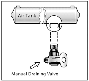
Figure 5-1
Compressed air usually has some water and some compressor oil in it, which is bad for the air brake system. For example, the water can freeze in cold weather and cause brake failure. The water and oil tend to collect in the bottom of the air tank. Be sure that you drain the air tanks completely. Each air tank is equipped with a drain valve in the bottom. There are two types:
- Manually operated by turning a quarter turn or by pulling a cable. You must drain the tanks yourself at the end of each day of driving. See Figure 5.1.
- Automatic--the water and oil are automatically expelled. These tanks may be equipped for manual draining as well.
Automatic air tanks are available with electric heating devices. These help prevent freezing of the automatic drain in cold weather.
5.1.5 - Alcohol Evaporator
Some air brake systems have an alcohol evaporator to put alcohol into the air system. This helps to reduce the risk of ice in air brake valves and other parts during cold weather. Ice inside the system can make the brakes stop working.
Check the alcohol container and fill up as necessary, every day during cold weather. Daily air tank drainage is still needed to get rid of water and oil. (Unless the system has automatic drain valves.)
5.1.6 - Safety Valve
A safety relief valve is installed in the first tank the air compressor pumps air to. The safety valve protects the tank and the rest of the system from too much pressure. The valve is usually set to open at 150 psi. If the safety valve releases air, something is wrong. Have the fault fixed by a mechanic.
5.1.7 - The Brake Pedal
You put on the brakes by pushing down the brake pedal. (It is also called the foot valve or treadle valve.) Pushing the pedal down harder applies more air pressure. Letting up on the brake pedal reduces the air pressure and releases the brakes. Releasing the brakes lets some compressed air go out of the system, so the air pressure in the tanks is reduced. It must be made up by the air compressor. Pressing and releasing the pedal unnecessarily can let air out faster than the compressor can replace it. If the pressure gets too low, the brakes won't work.
5.1.8 - Foundation Brakes

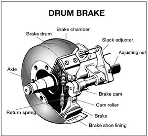
Figure 5-2
Foundation brakes are used at each wheel. The most common type is the s-cam drum brake. The parts of the brake are discussed below.
Brake Drums, Shoes, and Linings. Brake drums are located on each end of the vehicle's axles. The wheels are bolted to the drums. The braking mechanism is inside the drum. To stop, the brake shoes and linings are pushed against the inside of the drum. This causes friction, which slows the vehicle (and creates heat). The heat a drum can take without damage depends on how hard and how long the brakes are used. Too much heat can make the brakes stop working.
S-cam Brakes. When you push the brake pedal, air is let into each brake chamber. Air pressure pushes the rod out, moving the slack adjuster, thus twisting the brake camshaft. This turns the s-cam (so called because it is shaped like the letter "S"). The s-cam forces the brake shoes away from one another and presses them against the inside of the brake drum. When you release the brake pedal, the s-cam rotates back and a spring pulls the brake shoes away from the drum, letting the wheels roll freely again. See Figure 5.2.
Wedge Brakes. In this type of brake, the brake chamber push rod pushes a wedge directly between the ends of two brake shoes. This shoves them apart and against the inside of the brake drum. Wedge brakes may have a single brake chamber, or two brake chambers, pushing wedges in at both ends of the brake shoes. Wedge type brakes may be self-adjusting or may require manual adjustment.
Disc Brakes. In air-operated disc brakes, air pressure acts on a brake chamber and slack adjuster, like s-cam brakes. But instead of the s-cam, a "power screw" is used. The pressure of the brake chamber on the slack adjuster turns the power screw. The power screw clamps the disc or rotor between the brake lining pads of a caliper, similar to a large c-clamp.
Wedge brakes and disc brakes are less common than s-cam brakes.
5.1.9 - Supply Pressure Gauges
All vehicles with air brakes have a pressure gauge connected to the air tank. If the vehicle has a dual air brake system, there will be a gauge for each half of the system. (Or a single gauge with two needles.) Dual systems will be discussed later. These gauges tell you how much pressure is in the air tanks.
5.1.10 - Application Pressure Gauge
This gauge shows how much air pressure you are applying to the brakes. (This gauge is not on all vehicles.) Increasing application pressure to hold the same speed means the brakes are fading. You should slow down and use a lower gear. The need for increased pressure can also be caused by brakes out of adjustment, air leaks, or mechanical problems.
5.1.11 - Low Air Pressure Warning
A low air pressure warning signal is required on vehicles with air brakes. A warning signal you can see must come on before the air pressure in the tanks falls below 60 psi. (Or one half the compressor governor cutout pressure on older vehicles.) The warning is usually a red light. A buzzer may also come on.
Another type of warning is the "wig wag." This device drops a mechanical arm into your view when the pressure in the system drops below 60 psi. An automatic wig wag will rise out of your view when the pressure in the system goes above 60 psi. The manual reset type must be placed in the "out of view" position manually. It will not stay in place until the pressure in the system is above 60 psi.
On large buses it is common for the low pressure warning devices to signal at 80-85 psi.
5.1.12 - Stop Light Switch
Drivers behind you must be warned when you put your brakes on. The air brake system does this with an electric switch that works by air pressure. The switch turns on the brake lights when you put on the air brakes.
5.1.13 - Front Brake Limiting Valve
Some older vehicles (made before 1975) have a front brake limiting valve and a control in the cab. The control is usually marked "normal" and "slippery." When you put the control in the "slippery" position, the limiting valve cuts the "normal" air pressure to the front brakes by half. Limiting valves were used to reduce the chance of the front wheels skidding on slippery surfaces. However, they actually reduce the stopping power of the vehicle. Front wheel braking is good under all conditions. Tests have shown front wheel skids from braking are not likely even on ice. Make sure the control is in the "normal" position to have normal stopping power.
Many vehicles have automatic front wheel limiting valves. They reduce the air to the front brakes except when the brakes are put on very hard (60 psi or more application pressure). These valves cannot be controlled by the driver.
5.1.14 - Spring Brakes
All trucks, truck tractors, and buses must be equipped with emergency brakes and parking brakes. They must be held on by mechanical force (because air pressure can eventually leak away). Spring brakes are usually used to meet these needs. When driving, powerful springs are held back by air pressure. If the air pressure is removed, the springs put on the brakes. A parking brake control in the cab allows the driver to let the air out of the spring brakes. This lets the springs put the brakes on. A leak in the air brake system, which causes all the air to be lost, will also cause the springs to put on the brakes.
Tractor and straight truck spring brakes will come fully on when air pressure drops to a range of 20 to 45 psi (typically 20 to 30 psi). Do not wait for the brakes to come on automatically. When the low air pressure warning light and buzzer first come on, bring the vehicle to a safe stop right away, while you can still control the brakes.
The braking power of spring brakes depends on the brakes being in adjustment. If the brakes are not adjusted properly, neither the regular brakes nor the emergency/parking brakes will work right.
5.1.15 - Parking Brake Controls

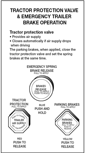
Figure 5-3
In newer vehicles with air brakes, you put on the parking brakes using a diamond-shaped, yellow, push-pull control knob. You pull the knob out to put the parking brakes (spring brakes) on, and push it in to release them. On older vehicles, the parking brakes may be controlled by a lever. Use the parking brakes whenever you park.
Caution. Never push the brake pedal down when the spring brakes are on. If you do, the brakes could be damaged by the combined forces of the springs and the air pressure. Many brake systems are designed so this will not happen. But not all systems are set up that way, and those that are may not always work. It is much better to develop the habit of not pushing the brake pedal down when the spring brakes are on.
Modulating Control Valves. In some vehicles a control handle on the dash board may be used to apply the spring brakes gradually. This is called a modulating valve. It is spring-loaded so you have a feel for the braking action. The more you move the control lever, the harder the spring brakes come on. They work this way so you can control the spring brakes if the service brakes fail. When parking a vehicle with a modulating control valve, move the lever as far as it will go and hold it in place with the locking device.
Dual Parking Control Valves. When main air pressure is lost, the spring brakes come on. Some vehicles, such as buses, have a separate air tank which can be used to release the spring brakes. This is so you can move the vehicle in an emergency. One of the valves is a push-pull type and is used to put on the spring brakes for parking. The other valve is spring loaded in the "out" position. When you push the control in, air from the separate air tank releases the spring brakes so you can move. When you release the button, the spring brakes come on again. There is only enough air in the separate tank to do this a few times. Therefore, plan carefully when moving. Otherwise, you may be stopped in a dangerous location when the separate air supply runs out. See Figure 5.3.
5.1.16 - Antilock Braking Systems (ABS)
Truck tractors with air brakes built on or after March 1, 1997, and other air brakes vehicles, (trucks, buses, trailers, and converter dollies) built on or after March 1, 1998, are required to be equipped with antilock brakes. Many commercial vehicles built before these dates have been voluntarily equipped with ABS. Check the certification label for the date of manufacture to determine if your vehicle is equipped with ABS. ABS is a computerized system that keeps your wheels from locking up during hard brake applications.
Vehicles with ABS have yellow malfunction lamps to tell you if something isn't working.
Tractors, trucks, and buses will have yellow ABS malfunction lamps on the instrument panel.
Trailers will have yellow ABS malfunction lamps on the left side, either on the front or rear corner. Dollies manufactured on or after March 1, 1998 are required to have a lamp on the left side.
On newer vehicles, the malfunction lamp comes on at start-up for a bulb check, and then goes out quickly. On older systems, the lamp could stay on until you are driving over five mph.
If the lamp stays on after the bulb check, or goes on once you are under way, you may have lost ABS control at one or more wheels.
In the case of towed units manufactured before it was required by the Department of Transportation, it may be difficult to tell if the unit is equipped with ABS. Look under the vehicle for the electronic control unit (ECU) and wheel speed sensor wires coming from the back of the brakes.

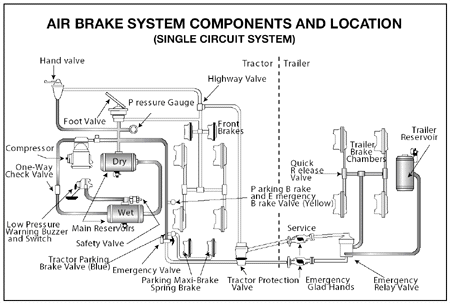
Figure 5-4
ABS is an addition to your normal brakes. It does not decrease or increase your normal braking capability. ABS only activates when wheels are about to lock up.
ABS does not necessarily shorten your stopping distance, but it does help you keep the vehicle under control during hard braking.
Subsection 5.1
Test Your Knowledge
- Why must air tanks be drained?
- What is a supply pressure gauge used for?
- All vehicles with air brakes must have a low air pressure warning signal. True or False?
- What are spring brakes?
- Front wheel brakes are good under all conditions. True or False?
- How do you know if your vehicle is equipped with antilock brakes?
These questions may be on your test. If you can't answer them all, re-read subsection 5.1.
Check out our Customer Reviews!


